Search Results
57 results found with an empty search
- 3D Printing vs. Injection Moulding: Which to Choose?
Injection moulding and 3D printing are the two most commonly used methods for manufacturing plastic parts, but it can be hard to decide which is most suitable for your project. Each manufacturing process has its own advantages and can be used together as complementary manufacturing methods. This guide compares the optimal uses of each. How do 3D printing and injection moulding work? 3D printing 3D printing, or additive manufacturing, is a process of making three-dimensional solid objects from a digital file. Essentially it prints by adding material one layer at a time, from the bottom up. Additive manufacturing can produce shapes and parts that are either difficult or even impossible to create using other fabrication methods, and an increasing variety of materials are available for use with this manufacturing process. Injection moulding Injection moulding uses moulds to manufacture parts. First, a mould is made of a temperature-resistant material in a reverse image of the part being produced. Once the mould has been manufactured, plastic is injected into the mould and allowed to cool, to produce the final part. With this process, multiple parts can be manufactured at once. How do 3D printing and injection moulding compare? Production volume The volume of the production run is a major deciding factor when deciding whether to use 3D printing or injection moulding. For high-volume production of identical parts (1000+) injection molding is the most effective and affordable. For low volumes (10-100+), 3D printing is more cost-effective. For mid-volume production, other factors including design complexity, turnaround time and customization must be taken into consideration. Design complexity There are many factors which need to be considered when designing for injection moulding, as the part must be able to be removed from the mould when it is complete. A complex design must be moulded in many pieces and subsequently fit together, and delicate areas must be treated with care. Generally, more complex designs are more expensive. With 3D printing, the parts are built layer-by-layer, which gives the designer a great amount of freedom when designing the part. A complex part is as easy and affordable to 3D print as a simple design. Production time Injection moulding has a long lead time because a mould must be designed and built for the part being manufactured. It generally takes 10-20 days to design and build the mould before the parts can be produced. With 3D printing, the CAD file is simply uploaded to the printer and is ready to build, with delivery times as low as 24 hours. Customization When injection moulding, a new mould must be built each time the design is changed. This can cost anywhere from ~$100 for a 3D-printed low-volume injection mould to $100,000+ for a complex steel mould for mass production. This makes design changes very expensive and time-consuming. With 3D printing, all modifications are made with 3D modelling software. The CAD file can be sent directly to the 3D printer to be manufactured, making modifications or custom designs very quick and easy to produce. This makes 3D printing very useful for applications such as designing and testing prototypes, creating customized consumer goods, and creating medical devices formed to the human body. Material strength The injection moulding process creates parts in one single piece, making it strong across all dimensions. With 3D printing the parts are built layer by layer, making the final part weaker along the layer lines. More recently developed 3D printing processes have minimized these weaker layers, and provide strength close to injection moulded parts. Parts requiring strength in a certain direction can be oriented in the print bed to provide strength in the desired direction, as shown in this video where a 3D-printed chain link is used to lift a car. Surface finish Injection moulded parts have a wider variety of finish options than 3D-printed parts. Injection moulded parts often undergo additional surface finishing to hide imperfections such as the flow lines, knit lines, sink marks and shadow marks that are a result of injection moulding. 3D printed parts can have a textured surface finish integrated into the design, but the finished part can show slight layer lines. These lines can be minimized if the part is oriented properly in the print bed. An additional step of post-processing is often used to smooth the parts to improve aesthetics or material properties. 3D printing and injection moulding in the manufacturing cycle Often 3D printing and injection moulding are both used in the product development and manufacturing cycle. A product can be designed and tested with 3D printed prototypes, and initial production runs can be manufactured with 3D printing until the production volume is high enough to justify the expense of injection moulding. In this case, the part can be designed for the injection moulding process so the transition between the two manufacturing processes is seamless. 3D printing is again used in the end-stage lifecycle of a product to create legacy parts for older or discontinued equipment. 3D printing can also be used to create moulds for injection moulding, or create unique parts such as jigs and fixtures. Summary Conclusion Both injection moulding and 3D printing serve different and complementary purposes in manufacturing. When choosing which one to use, it is important to consider which factors are most important, including cost, production volume, delivery time, material properties and your stage in the design and manufacturing process.
- How Cerakote is Used in Additive Manufacturing to Enhance the Performance of 3D Printed Parts
Cerakote Ceramic coating is a world-leading thin-film coating that is applied to plastic, metal and other materials to enhance their physical performance and appearance including scratch resistance, wear resistance, waterproofing, chemical resistance, and UV protection. Industrial Applications of Cerakote The performance-enhancing properties of Cerakote make it a logical choice for a wide variety of industries and manufacturing processes. For example, Cerakote is used for corrosion protection in the oil and gas industry, heat resistance in the aerospace sector, performance coatings in the automotive industry, extending the life of sporting and hunting equipment, and increasing the useful life of jigs and fixtures. Recommended applications include tools, consumer goods, eyeglasses, sporting equipment, robotics, electronics, fresh and saltwater applications and other applications where a durable performance coating is required. A wide variety of manufacturers and suppliers rely on Cerakote coatings including Boeing, SpaceX, Blue Origin, Lockheed-Martin, US Department of Defence, Zipline, Ford, and Lamborghini. Benefits of Cerakote Destructive testing has shown the superiority of Cerakote to other standard finishes. For example, a Taber abrasion wear test was performed by NIC Industries to compare the durability of Cerakote to 6 other popular coatings. In this test, Cerakote lasted nearly twice as long as the nearest competitive finish and 24 times as long as the furthest competitive finish. Another study tested the impact resistance of Cerakote. In this test, a 1 oz slug was fired from a 12-gauge shotgun at a piece of metal plate treated with Cerakote. The area behind and surrounding the impact site showed no cracking or loss of adhesion, even in the areas of greatest deformity. Cerakote in Additive Manufacturing of Plastic Parts Cerakote is an increasingly popular finish used in additive manufacturing because it’s ability to enhance the performance and aesthetics of 3D printed plastic parts. This diversifies the potential end-use applications of the parts; for example, Cerakoted plastics are emerging as faster, less expensive alternatives to metal parts, especially for small-to-medium volume manufacturing. An example is provided in this case study, where HP and Aerosport re-designed 2 different metal assemblies to be 3D printed with Nylon 12. Each was able to reduce assembly time, weight, cost of manufacturing and overall production times by a significant amount. To validate the performance of Cerakote when applied to 3D-printed plastic parts, the Cerakote Technical Training Team completed ASTM testing on Nylon PA12 plastic coated with 2 different types of Cerakote finishes. The tests showed excellent results, including no chipping or cracking in cross-hatch adhesion tests, and minimal effect after 24 hour immersion in water, acetone or diesel. Get Started With Cerakote Coating for 3D Printed Parts Tempus 3D is a qualified Cerakote applicator located in British Columbia, Canada. Tempus offers Cerakote finishing for clients across Canada and the US, both as an extension of it’s additive manufacturing business and as an independent service. If you are interested in learning more about Cerakote,and it's use in manufacturing you can visit our guide to Cerakote at www.tempus3d.com/cerakote-finish-for-3d-printed-parts. To request a quote, please contact our team at info@tempus3d.com or through our contact us page.
- How to Design for Accuracy with HP Multi Jet Fusion
With every 3D printing technology there are strategies to get the best result with your print. When designing parts for HP Multi Jet Fusion, it is possible to achieve very fine dimensional accuracy, with Cpk values comparable to injection molding. HP has provided a set of guidelines to help maximize the accuracy of your design. Minimum Specifications The recommended minimum dimensions for printed features are between 0.1 mm and 0.5 mm Minimum hole diameter 0.5 mm Minimum shaft diameter 0.5 mm Minimum printable font size 6 pt Minimum printable features or details (width) 0.1 mm Minimum clearance 0.5 mm Minimum slit between walls/embossed details 0.5 mm Embossed and Engraved Details Text, numbers or drawings should be at least 1 mm deep. Additional Considerations When designing for detail, there are several other considerations to keep in mind. When possible, place small features with critical dimensions—such as pins, holes, and raised texts—in the same plane. Design parts with a smooth cross-section transition. When possible, lighten parts and minimize the chance of warpage by hollowing them or adding internal lattices. Avoid long, thin, flat parts with a ratio of length to width greater than 10:1. Avoid predominantly long and thin curved segments in your part design. Avoid ridges and ribs on large, flat areas. Learn more about Designing for Additive Manufacturing To learn more about how to design for additive manufacturing, visit Tempus 3D's design guide where you can find more best practices tips plus how to design for aesthetics, interlocking parts, and hinge design. Additive Manufacturing with Tempus 3D When you are ready to put your idea into reality, please reach out to the team at Tempus 3D. As one of only a handful of HP Certified Multi Jet Fusion 3D Printing Professionals in Canada, Tempus 3D has the technology, skills and service to provide you with consistently high-quality parts, quickly and affordably. You can access online quotes through Tempus 3D's instant quote page, or learn more about our materials, services, and access case studies and customer success stories through our website at www.tempus3d.com.
- Choosing the best material for 3D printing with HP Multi Jet Fusion
Whether you are building prototypes or end-use parts, your material choice will depend on the characteristics you want your finished object to have. Learn about the materials available for HP Multi Jet Fusion, the advantages of each, and how they compare*. One of the most important questions to answer with 3D printing is what material is best fit for your specific end-use application. 3D printing allows for a wide range of materials to be used, each of with a variety of characteristics and capabilities. With HP Multi Jet Fusion (MJF), you have a variety of plastic polymers to choose from. The Multi Jet Fusion priinting process produces consistently precise, robust results, but each material choce has specific advantages including stiffness, elongation at break, water resistance, chemical resistance and biocompatibility. These can be sub-categorized as rigid polymers, which have a low-to-medium stiffness, elongation, and rigidity; and elastomeric polymers, which have a high elastic elongation and high flexibility to minimize breaking or cracking. Rigid 3D Printing Polymers HP Nylon PA12 HP Nylon PA12 is an all-purpose 3D printing material ideal for producing strong, low-cost, quality parts and functional prototypes. Robust thermoplastic produces high-density parts with balanced property profiles and strong structures. Provides good chemical resistance to oils, greases, aliphatic hydrocarbons, and alkalies. Ideal for complex assemblies, housings, enclosures, and watertight applications. Biocompatibility certification - meets USP Class I-VI and US FDA guidance for Intact Skin Surface Devices. Designed for production of functional parts across a variety of industries. Achieves watertight properties without any additional post-processing. Reliably produce final parts and functional prototypes with fine detail and dimensional accuracy. Learn more about Nylon PA12 Case Study - Dustram Chipping Hammer Case Study - Air Force Velocity Snowmobile Parts HP Nylon 12 Glass Bead Nylon 12 Glass Bead is ideal for producing stiff, dimensionally stable, quality parts. Filled with 40% glass bead to provide dimensional stability. Ideal for applications requiring high stiffness like enclosures and housings, fixtures and tooling. Designed for production of functional parts across a variety of industries. Engineered to produce common glass bead applications with detail and dimensional accuracy. Learn more about Nylon PA12 Glass Bead HP Polypropylene (PP) HP Polypropylene is ideal for functional parts with low moisture absorption and chemical resistance. Versatile material ideal for a wide range of automotive, industrial, consumer goods, and medical applications. Excellent chemical resistance and low moisture absorption makes this material ideal for piping or fluid systems and containers. Outstanding welding capabilities with other polypropylene parts produced with traditional methods like injection molding. Biocompatibility—meets ISO 10993 and US FDA guidance for Intact Skin Surface Devices Statements. Learn more about HP Polypropylene HP Nylon PA 11 Nylon PA11 is ideal for producing ductile, quality parts. Provides excellent chemical resistance and high elongation-at-break. Impact resistance and ductility for prostheses, insoles, sports goods, snap fits, living hinges, and more. Bio-compatibility: meets USP Class I-VI and US FDA guidance for Intact Skin Surface Devices. Renewable raw material from vegetable castor oil (reduced environmental impact). produce final parts and functional prototypes with fine detail, and dimensional accuracy. Flexible 3D Printing Polymer Elastomeric polymers have a high elastic elongation and high flexibility to minimize breaking or cracking. BASF Ultrasint TPU Ideal for producing flexible, functional parts. Excellent rebound resilience and elongation-at-break. Optimal mechanical resistance at low temperatures. Ideal for applications like winter sports equipment, car interiors, robotics and grippers, and fluid systems. High level of detail. Robust parts withstand abusive environments. Learn more about Ultrasint TPU01 Explore TPU use cases HP 3D Printing Materials Comparison Chart The following chart provides a quick comparison of materials produced with the HP Multi Jet Fusion 5200 3D printer. HP Multi Jet Fusion 3D Printing with Tempus 3D When you are ready to put your idea into reality, please reach out to the team at Tempus 3D. As one of only a handful of HP Certified Multi Jet Fusion 3D Printing Professionals in Canada, Tempus 3D has the technology, skills and service to provide you with consistently high-quality parts, quickly and affordably. You can access online quotes through Tempus 3D's instant quote page, or learn more about our materials, services, and access case studies and customer success stories through our website at www.tempus3d.com. *All information and images courtesy of HP.
- Prensilia and Elastico Disegno bring functionality and aesthetics to robotic prosthetics
The design freedom and quality materials provided by HP Jet Fusion 3D Printing Solutions allow Prensilia and Elastico Disegno to create a robotic hand called ‘Mia’ In 2012, Prensilia set itself the goal of developing a robotic hand casing that was light, highly functional, aesthetically pleasing and structurally solid to protect the internal mechanical and electronic components of the device. For this project, Prensilia collaborated with Elastico Disegno to help them overcome the limits set by traditional production methods and other filament-based 3D printing technologies, such as the inability to perfectly adapt the external covers to the shape of internal mechanics, while maintaining exceptional surface quality. Elastico Disegno chose to use PTC Creo because it is able to design mechanical and anatomical parts in a single environment, thus accelerating development and minimizing the number of components required, flexibly size the product to adapt to any variation of the components, communicate directly with the technical development departments, and simply exchange data with the customer to speed up design operations. The result of this innovative project is Mia, a robotic hand equipped with sensors and connected to a trans-radial titanium implant (between the elbow and the wrist). The cables and electrodes that connect the muscles and nerves pass through the two bones of the forearm (the ulna and the radius) before reaching the robotic hand, returning the information captured by the fingers and improving movement. Due to the complexity of most of Mia's components, Prensilia and Elastico Disegno saw additive manufacturing as the only valid technology for this project. The external coatings of the hand and fingers are made with HP Multi Jet Fusion technology using HP nylon PA 12 material, which combines strength and structural support, as well as a surface finish able to guarantee the desired aesthetics from Prensilia. These components include wearing parts, such as buttons and snap fasteners, which have passed all functionality tests. The soft parts of Mia's fingertips are made from silicone molds, also made by HP Multi Jet Fusion and Nylon 12. According to Prensilia, replacing metal molds with plastic molds has reduced the investment required and production times, without compromising performance and external finish. Marco Controzzi, Founder of Prensilia, described their reaction to the final product. “The first time we tried Mia on a patient, the reaction was, ‘How light!’,” she said. “We reached the desired level of robustness thanks to the improvement of the internal mechanics and by 3D printing the external casing with HP Multi Jet Fusion, which allows for the combination of rigidity and surface finish.” Controzzi also sees the ability to rapidly iterate as a major advantage of HP Multi Jet Fusion technology. “Another important advantage offered by 3D printing to technological frontier products such as ours is the possibility of offering customers updated products,” Controzzi said. In 2019, Mia received the Red Dot Award, one of the world's largest and most important design awards for product design. Additive Manfuacturing with Tempus 3D As one of only a select few HP Certified Production Professionals in Canada, Tempus 3D can help you achieve the advantages of additive manuafcturing with Multi Jet Fusion. Contact us today to learn more about our on-demand 3D printing service. Note: original case study and photos courtesy of HP Read the full HP case study Explore more case studies and articles with Tempus 3D Printing Learn more about HP Multi Jet Fusion aditive manufacturing services with Tempus 3D
- How to Design for HP Multi Jet Fusion
Each 3D printing technology has a unique set of design recommendations to ensure the best result. We would like to share the design specifications provided by HP for their HP Multi Jet Fusion 3D printing technology to help you achieve the best results possible. These design guidelines apply to all Multi Jet Fusion materials, including Nylon PA12, Nylon PA12 Glass Bead, Polypropylene, and TPU Flexible Polymer. What is HP Multi Jet Fusion (MJF)? Before starting, it helps to understand what HP Multi Jet Fusion (MJF) is and how it differs from other 3D printing technologies. According to HP, The MJF printing process is a combination of Powder Bed Fusion and binder jetting technologies. Unlike SLS or FDM, which use a point-by-point printing approach, HP MJF technology can print a complete layer at the same time. A layer of powder material is spread on the print bed, then fusing and detailing agents are deposited at voxel-level on top of the powder. These define the regions of the layer that need to be fused or protected from fusion respectively. The bed is heated and the areas where the fusing agent was deposited are fused together.. Once these fused layers cool down, they solidify to form the designed 3D-printed part. Wall thickness When you’re creating a 3D design for Multi Jet Fusion, the minimum recommended wall thickness is 0.3mm for short walls oriented in the XY plane, and 0.5mm for short walls oriented on the Z plane. If you design your part to be optimized for a specific orientation, make sure you make this clear to the person or company printing your part. Cantilevers When printing a cantilever, the minimum wall thickness depends on the aspect ratio, which is the length divided by the width. For a cantilever with a width of less than 1mm, the aspect ratio should be less than 1. There are no specific recommendations for widths of 1mm or larger, but for parts with a high aspect ratio, it is recommended to increase the wall thickness or to add ribs or fillets to reinforce the part. Connecting Parts Sometimes a pair of printed parts need to fit together to form the final application. To ensure correct assembly, a good starting point would be to leave a gap between the interface areas of these parts of 0.4 mm (+/- 0.2 mm for each part). Moving Parts As a general rule, spacing and clearance between faces of parts printed as assemblies should be a minimum of 0.7mm. Parts with walls which are 30mm or thicker should have a larger gap between each side to ensure proper performance. Parts with walls that are thinner than 3mm thatcan have a clearance as low as 0.3mm, but this depends on the design. Testing may be necessary to ensure quality performance. Thin or Long Parts Thin and long parts are susceptible to non-uniform cooling, which may cause uneven shrinkage along the printed part. This can warp the part from it's original shape. The potential for warpage can be minimized with good design practices. A general guideline is that any part with an aspect ratio higher than 10:1, an abrupt change in its cross-section, or a predominantly long and thin curved segment is susceptible to warpage. These include thin and long parts; parts with abrupt changes in cross-sections; and thin and curved surfaces. To minimize the possibility of deformation, there are several guidelines to follow when designing the part. These include: Increase the thickness of long walls to reduce their aspect ratios. Avoid ridges and ribs on large, flat areas. Re-design parts with high potential stress and smoothen their cross-section transitions. Lighten the parts by hollowing them or by adding internal lattices. Hollow Parts For large or thick parts, it is recommended to minimize the risk of warping by hollowing the part or adding an internal lattice structure. The minimum recommended wall thickness is 2mm, but better mechanical properties are achieved with thicker walls. The optimum choice is dependent upon the application. Hollowing can be easily achieved with professional software such as SolidWorks, Materialise Magics, Autodesk and Netfabb. Depending on the end-use application, the part can be left solid, or drain holes can be added to remove the powder in the post-processing process. Ensure the drain holes are at least 4 mm wide if there is a single drain hole, or 2+ mm wide for multiple escape holes. When placing the holes ensure they are placed in a way that forced air can be used to effectively clean out trapped powder. If no escape holes are provided and powder remains within the part, the part will be heavier and stronger than with the fully hollow option. Leaving the powder trapped within a part also saves post-processing time since powder extraction is not required. Lattice structures Lattice structures are used in thick or large parts to minimize the chance of warping or for producing lighter parts. Replacing solid materials with a lattice also reduces the cost to 3D print the part. This design optimization strategy involves hollowing a part and replacing the internal solid mass with a lattice structure that provides mechanical integrity. This re-design can be automated with professional software such as Materialise Magics or nTopology. Additional Considerations Material Choice Each type of material that is 3D printed with HP Multi Jet Fusion has different properties. Select your material based on the properties you desire such as strength, flexibility, biocompatibility, weather resistance, or chemical resistance. File Resolution The resolution of your file is an important factor to consider when 3D printing your part. If your file is too low resolution it may lack quality, and if the resolution is too high then the file size may be too large for the printer to read. Keep your file size under 100MB if you can. HP Multi Jet Fusion 3D Printing with Tempus 3D For additional advice on how to design for HP Multi Jet Fusion, you can take a look at the guidelines provided by Tempus 3D on our design guidelines page. Here you will find details regarding dimensional tolerances for different design features, guidelines to optimize your print accuracy and aesthetics, and details such as how to design for interlocking parts and hinges. As an HP Certified Multi Jet Fusion 3D Printing Professional, Tempus 3D has the technology, skills and service to provide you with consistently high-quality parts, quickly and affordably. When you are ready to put your idea into reality, you can access online quotes through Tempus 3D's instant quote page, or learn more about our materials, services, and access case studies and customer success stories through our website at www.tempus3d.com. note: all photos and design guidelines are provided by HP.
- Biesse Advances it's Design and Development with HP Multi Jet Fusion 3D Printing Technology
How Biesse has increased design freedom, improved speed-to-market, and met customer requirements more quickly and more profitably with industrial 3D printing technology. The Biesse Group was founded in Pesaro, Italy in 1969 by Giancarlo Selci. The company offers modular solutions from the design of turnkey systems for large furniture manufacturers to individual automatic machines and workstations for small and medium-sized businesses. The company has a variety of subsidiaries which design, manufacture and market a full range of technologies and solutions for the wood industry, including furniture, windows and other wood components. Biesse has also recently expanded to plastic processing machines, with solutions designed specifically for this growing market. Challenge “Within Biesse, we have a business unit entirely dedicated to the supply of machines that allow edging“, says the company's technical and prototype office manager, Marco Mencarini.“They allow the application of plastic or wood to the edges of the furniture. As you can imagine, our machines have to support a diverse set of assembly needs. To support them, we need to create a wide range of highly customized parts and tools.” Some Biesse edgebanding machines operate at very high speed and consist of many moving parts that help the customer guide the edge through the assembly using supports, channels and guides. In many cases, these production aids have to be tailored to the beading material used.The challenge they faced was the ability to quickly and affordably design and build these customized pieces. Solution Biesse uses a variety of manufacturing processes in it's product development, including 3D printing. “We’ve worked with 3D printing since late 1990’s, primarily for rapid prototyping,” says Mr. Mencarini. “The HP Jet Fusion 3D Printing Solution allows us to do much more, including helping us bridge the lead-time gap of making metal molds and even allowing us to produce final parts, especially in short-runs that would be impossible to profitably manufacture otherwise.” As 3D printing has matured, they have continually explored new opportunities. When HP launched its first HP Multi Jet Fusion 3D printers, Biesse became one of the first to adopt an HP Jet Fusion 3D 4200 printer. The company chose HP because HP's Multi Jet Fusion technology meets a variety of needs. In addition to simple models, Biesse wanted a more efficient way to create functional prototypes of its various mechanical components, including connecting rods, pulleys, sprockets, couplings and other parts. An example is the gear box pictured below. The part initially required multiple manufacturing technologies, including injection molding and computer numerical control (CNC) machining. Biesse's engineers wanted to assess whether the part could be redesigned using 3D printing. The design and manufacturing team optimized the geometry of the part in ways that couldn't be made with traditional manufacturing processes, such as CNC machining and injection molding), creating a part that was more efficient and less expensive part to produce usign HP Multi Jet Fusion 3D printing technology. Result With creative part redesign and HP Multi Jet Fuison 3D printing processes, The Biesse team was able to reduce the lead times required to create and improve their products. They found significant productivity gains over other other 3D printing technologies and over traditional manufacturing techniques. This technology allows Biesse to beta-test a series of parts in hours rather than weeks. The quality of the parts features excellent surface quality, allowing Biesse to sandblast and paint parts comparable to other parts that are injection molded or computer numerically controlled (CNC) machined. Biesse compared the cost and time savings to manufacture a series of 100 of these mechanical parts with HP Multi Jet Fusion (MJF), CNC machining, and injection molding. Their results showed significant advantages of MJF over traditional manufacturing processes, as summarized below. HP Multi Jet Fusion CNC Injection Molding cost: 100% cost: 300% cost first year: 700% lead time: 1 day lead time: 20 days cost from year 2: 20% lead time: 90 days This case study, originally published by HP and Biesse, shows the potential for additive manufactuing with HP Multi Jet Fusion technology to revolutionize the manufacturing industry, saving companies significant time and money. Additive Manufacturing with Tempus 3D As one of only a select few HP Certified Production Professionals in Canada, Tempus 3D can help you achieve the advantages of additive manufacturing with Multi Jet Fusion. Contact us today to learn more about our on-demand 3D printing service, or get an online quote. Note: Case study and photos courtesy of HP and Biesse. Read the full HP case study Explore more case studies and articles with Tempus 3D Printing Learn more about HP Multi Jet Fusion aditive manufacturing services with Tempus 3D
- Canadian Medical Service Provider 3D Prints Custom Medical Devices with the Support of Tempus 3D
Montreal-based medical services innovator uses 3D printing technology to develop custom form-fitted and breathable back braces to improve patient comfort and outcomes. A medical services innovator based in Montreal, Quebec approached Tempus 3D with a back brace design that they wanted to have manufactured. After comparing 3D printing service providers, they approached Tempus 3D for a solution. Challenge The biggest challenge with this project was the large size of the brace. Not many industrial 3D printers are capable of manufacturing such a large piece, and when a part has large, flat areas there is a risk of the piece warping during the manufacturing process. A second consideration was to choose a medical-grade material with the strength, durability and flexibility to provide comfortable support. Solution The team at Tempus 3D was able to leverage HP Multi Jet Fusion 3D printing technology, which provides the class-leading build volume and part quality required to successfully manufacture this design. With this printer all of the parts for the brace could all be fit into one print run, which saved manufacturing time and cost. The greatest risk in the production of the brace was the potential for the pieces to warp, because the difference in temperatures across large, flat pieces can bend them as they cool. The team at Tempus 3D collaborated with experts at HP and Hawkridge Systems to ensure the part orientation and print settings were optimized for the best result. The other consideration in building the brace was to select a material that was suitable for a medical device used on or near the skin. Nylon 12 was the material of choice because it has high tensile strength, is waterproof, and is certified biocompatible. It also has enough flexibility to accommodate the patient's movement without losing its support. Result In collaboration with their manufacturing network, the team at Tempus 3D was able to produce a brace that exceeded the client's expectations in terms of finish, color, accuracy, and cost. We at Tempus are excited to help local businesses meet their manufacturing goals as a part of the industry 4.0 network which allows innovators across sectors to bring products to market quicker and in a more environmentally friendly way. Learn more about designing for 3D printing with HP Multi Jet Fusion 3D printing technology Explore industrial plastics available through Tempus 3D Learn more about the advantages of industrial 3D printing with HP Multi Jet Fusion technology Explore more case studies and articles
- Ledcor replaces hard-to-find valves and improves part design with help from Tempus 3D Printing
Ledcor teams up with Tempus 3D printing to alleviate supply chain issues, improve part design and minimize manufacturing time. Ledcor is North American construction company which was having trouble finding replacements for ball valves used in applying calcium chloride to road surfaces for dust control and other purposes. After making exhaustive attempts to source new valves through their traditional suppliers they were faced with a six month or greater lead-time for delivery. Ledcor approached Tempus for a solution, with the explicit need to get a functioning ball valve in their hands within four weeks. They also wanted to take the opportunity to improve the design of the valve to address historical weak points and improve functionality. The main weak point had been the seam in the parts from where the two injection molded parts had fit together. This seam was prone to holding water and then freezing during the cold Canadian winters, which resulted in the parts cracking and no longer holding a seal. The team at Tempus 3D collaborated with their partners at the Selkirk Technology Access Centre (STAC) part of Selkirk Innovates team (www.selkirk.ca/innovates) to re-design the part and manufacture the final product within the specified timeline and deliverables. The original valve was scanned with a Creaform HandySCAN 3D scanner to determine the critical dimensions, and the part was redesigned to improve it’s function and address critical failure points. A prototype of the valve casing was 3D printed and tested for fit and function. After additional design changes, the final product was manufactured using an HP Multi Jet Fusion 5200 3D printer for it’s dimensional accuracy and quality. Nylon PA 12 was selected as the material for its overall durability and resistance to water, chemicals and UV rays. Once printing was complete was sealed with AMT Post Pro vapour smoothing technology to improve water and chemical resistance. Finally, due to the tight dimensional requirements and fit, the low-tolerance surfaces of the valve were machined to ensure exact compliance with the client specifications. This whole process was completed in less than four weeks, and future parts could be manufactured and delivered in less than two weeks. The cost savings to Ledcor were significant, both in terms of saved downtime and overall cost of manufacturing in comparison to the alternative options of injection molding or CNC machining. Ledcor and Tempus continue to look for ways to integrate 3D printing into their operations to reduce their supply chain risk and improve part functionality and quality. With Tempus’ location in the interior of British Columbia, it is uniquely capable of serving markets across Western Canada with cost-effective overnight shipping and the ability to turn around rush orders in as little as 36 hours. We at Tempus feel this is just the beginning of what manufacturing will look like in the future; it will be more responsive, more custom, and more local allowing innovators across sectors to bring products to market quicker and in a more environmentally friendly way. Learn more about the advantages of industrial 3D printing with HP Multi Jet Fusion technology Learn more about reverse engineering with 3D scanning Explore industrial plastics available through Tempus 3D Explore more case studies and articles
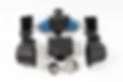
- How Dundon Motorsports improved part design for Porsche GT Racecars with HP MJF Technology
With the HP Jet Fusion 5200 Series 3D Printing Solution, Dundon Motorsports has been able to accelerate production, experiment with new designs, grow their product portfolio, and expand to new markets. Dundon Motorsports provides high-performance parts to the motorsports world. One of Dundon's projects was to upgrade the performance and horsepower of Porsche GT racecars. According to Dundon Motorsports’ Jamie Bopp, “The nature of the car has been about freedom, about emotional release, about joy, so Dundon is in the business of taking joyful cars and making them more joyful.” Challenge The challenge in this project was to ensure the upgraded parts fit under the hood and within the confines of air conditioner, the power steering pump, and other parts. The other challenge was to ensure the design and manufacturing of the parts was time- and cost-effective. “Finding an innovative way to make all of these parts fit is one thing,” said Bopp. “The second thing is the business side of the situation. If we were able to injection mold or CNC machine these parts, the costs would be stratospheric.” Dundon looked into various manufacturing methods to produce an intake manifold, including injection molding and CNC machining. Injection molding would cost nearly $65,000 to produce a mold, which was prohibitively expensive, especially for low-volume manufacturing. CNC machining was not ideal because the tooling is difficult to control in the long, hollow parts due to the long reach of the tool and the vibration on the tool bit. also, aluminum was not ideal to manufacture the part because it transfers heat too easily to the intake air. as an alternative, they looked into 3D printing as a manufacturing option. Solution Dundon chose to work with 3D printing as a manufacturing option because the same technology could be used for both prototyping and final production of the parts. After researching the various options, they chose HP Multi Jet Fusion 3D printing technology for its capacity and repeatability. Their material of choice for building the parts is HP Nylon 12, for it's all-purpose robustness and ability to provide an air-tight seal. According to Bopp, “With [HP] MJF, we’re able to not just make a single-printed usable part, but we’re also able to make assemblies that we bolt together to adapt to what we would want to make in the end”. Result Dundon now produces many different parts with HP Multi Jet Fusion technology including intake plenums, intake runners, and air filter boxes. With this manufacturing method they are also able to easily alter the designs to improve functionality. Bopp sees HP 3D Printing as a disruptive technology in the industry. “We can draw a part and, within a few days to a week, have that part in our hands and be testing it on a car, when previously it’s taken development cycles that were quarters, months, at best cases, weeks. If we need to make a change, we can now make that change in days... [HP Multi Jet Fusion] has become an enabler for us. It has enabled us to operate and ‘punch above our weight class’ quite effectively.” Additive Manufacturing with Tempus 3D As one of only a select few HP Certified Production Professionals in Canada, Tempus 3D can help you achieve the advantages of additive manufacturing with Multi Jet Fusion. Contact us today to learn more about our on-demand 3D printing service, or get an online quote. Note: Case study and photos courtesy of HP and Biesse Motorsports. Read the full HP case study Learn more about HP Multi Jet Fusion and Nylon PA12 Learn more about HP Multi Jet Fusion additive manufacturing services with Tempus 3D
- Innovation Funding Opportunity for Entrepreneurs from Tech-Access Canada
Good day fellow entrepreneurs, The team at Tempus 3D wanted to share an opportunity that may be of interest to companies involved in technological innovation. Tech-Access Canada is a non-profit organization that supports the pan-Canadian network of 60 Technology Access Centres (TACs). They are currently offering an Interactive Visit Initiative (iVisit) that offers small businesses the opportunity to work with one of Canada’s 60 Technology Access Centres (TACs) to solve an innovation challenge. The areas they focus on include: Evaluating technical/economic feasibility of new products, processes, or services. Short-term R&D assistance and prototype development. Providing access to cutting-edge technology a company doesn’t have in-house. Providing objective scientific, technical, and business advice. Canada's TAC's are applied research and development centers affiliated with publicly-funded colleges. These centers are designed to help small businesses get more innovative and productive. Tempus 3D works in collaboration with the Selkirk Technology Access Center on a variety of projects, but depending on your location you may want to connect with a TAC closer to home. If you think that this opportunity would be of value to your company you can visit Tech Access Canada to learn more about the Interactive Visit program or submit an application form. We have provided links below. Hope this helps some of you with your research and development projects, and if not feel free to pass this on if you know someone this program may be of value to. Keep innovating, From the team at Tempus 3D Overview of the TAC Interactive Visit Program: https://tech-access.ca/resources/overview-interactive-visits-with-tacs/ Interactive Visit Request Form https://interactivevisits.ca/iVisit/Create
- All about HP Multi Jet Fusion 3D Printing
Multi Jet Fusion is a 3D printing process that is designed to build functional prototypes and manufacture low-to-mid volume production runs of end-use parts. This technology has become one of the leading additive manufacturing technologies for industrial applications because it can quickly and consistently manufacture parts with high tensile strength, fine detail, and overall excellent material properties. This article explains how Multi Jet Fusion works and it's unique advantages. How does HP Multi Jet Fusion technology work? HP Multi Jet Fusion (MJF) uses a powder-bed fusion 3D printing process, in which small powder particles (with a size of 30 nm) are fused together with heat. To build the parts, a fine layer of powder is deposited in the build chamber. A fusing agent is applied in select areas, creating a 2-dimensional profile of the part. Next, the fusion agent is heated with infrared light, which fuses the particles together and to the layers below. An additional agent is used to define the edges of the part and ensure dimensional accuracy. When a layer is finished, another layer of powder is deposited and the process is repeated. When the part is finished, the excess powder is removed and the parts are cleaned with a bead blaster. At this point the parts are ready for use or may receive further treatment to enhance their looks or material properties. Parts may also be machined for higher precision on features like mating surfaces, holes or internal threads. Advantages of Multi Jet Fusion Multi Jet Fusion is ideal for building prototypes that can be used in their end-use application and for small-to-medium volume production of final parts. The materials used in Multi Jet Fusion have characteristics that make them valuable for a wide variety of applications, including biocompatibility, chemical resistance, and resistance to water and UV degradation. They are used in a wide variety of industries including automotive, aerospace, medical devices, education, electrical, and robotics. How does HP Multi Jet Fusion compare to other 3D printing technologies? HP MJF is most commonly compared to Select Laser Sintering, also known as SLS. Both 3D printing technologies use heat to fuse layers of fine powder layer-by-layer in a build chamber, but they differ in the way heat is applied. With SLS, a laser heats the shape of the part being manufactured, point-by-point. With MJF, infrared lights heat the whole surface in one pass. The method of manufacturing directly affects the mechanical properties of the parts being printed and the speed of manufacturing. With SLS, the printing speed depends on how many parts are being built. A laser has to draw the surface of each model separately. This is an advantage when just only one part is printed, but with larger print volumes SLS takes longer than MJF. This also results in a higher cost for larger print volumes. With Multi Jet Fusion, the printing speed is the same no matter how many parts are being printed because the time needed to make each layer is the same. This provides a cost and speed advantage when many parts are printed at once and the whole build volume is filled. Usually, low-volume production is more cost-effective on HP printers. Multi Jet Fusion Materials One major advantage of Multi Jet Fusion is the ability to print a variety of materials, each with unique advantages. Nylon Polyamide 12 (Nylon 12) Nylon 12 is an excellent all-purpose material with properties that make it useful for a variety of applications. These include chemical resistance, water and UV resistance, and biocompatibility. Nylon 12 is the most commonly used material produced with HP Multi Jet Fusion. Nylon 12 with glass beads (Nylon GB) Nylon GB material is filled with 40% glass microspheres. It has all of the great material properties of Nylon 12, but the glass beads increase stiffness adn improve dimensional accuracy and reduce the possibility of warping with flat parts. Nylon GB is commonly used for thin, rigid parts such as casings and housings, fixtures and tools. Thermoplastic Polyurethane (TPU) TPU creates durable, strong,flexible parts. It is commonly used for applications where shock absorption capacity, flexibility or energy return is required.It has many applications including car interior components, industrial tools, pipes, grippers, footwear, orthopedics and sports protection equipment. Nylon Polyamide 11 (Nylon 11) Nylon 11 is a strong and flexible, producing high-density parts with fine detail and high accuracy. It is biocompatible and resistant to oils and greases. It is also stable to UV light and weather, and has good elasticity and impact resistance. Polypropylene (PP) Polypropylene is chemical resistant and weldable, with low moisture absorption and great mechanical properties. Polypropylene is an excellent choice for anything that needs to be light, water-tight, and durable. It is one of the most common polymers you find around the house, often used for plastic containers. What is the Digital Manufacturing Network? HP has established a digital manufacturing network with service providers certified as HP Multi Jet Fusion Production Professionals. The Digital Manufacturing Network (DMN) is a very select group of production-capable suppliers of Multi Jet Fusion parts, as certified by HP. HP set a standard of very high quality in printed parts that DMN members must meet for solutions engineering, production capacity, consistency, quality and repeatability of prints. Multi Jet Fusion 3D printing with Tempus 3D If you are looking for a local manufacturer, Tempus is one of a select few based in Canada that has been evaluated and qualified based on our end-to-end 3D printing capabilities for production at scale, as well as our manufacturing and quality processes. At Tempus 3D, our production team is fully certified in part quality optimization, and ready to support you through the prototype-through-production process quickly and cost-effectively. Visit us at tempus3d.com to learn more, or get a free quote with our online quote and ordering system. We look forward to supporting you in your innovation goals.